| Table of Contents |
|---|
Introduction
...
Technical data
A comparison of the technical data for NIC 50-RE and NIC 52-RE can be found in the netIC - Design guide and User manual in the section "Technical Data".
...
| NIC 50-RE | NIC 52-RE | |
|---|---|---|
| FLASH | 4 MB serial Flash EPROM | 4 MB Quad SPI Flash |
| Supported Protocols | PROFINET IO Device | PROFINET IO Device |
| Ethernet IP Adapter | Ethernet IP Adapter | |
| EtherCAT Slave | EtherCAT Slave | |
| Sercos 3 Slave | Sercos 3 Slave | |
| Open Modbus TCP | Open Modbus TCP | |
| Powerlink Slave | Powerlink Slave | |
| Varan Slave | CCLIE Slave | |
| Power supply: | ||
| Current at 3,3 V (typically) | 400 mA | 450 mA |
| Power consumption | appr. 1.3 W | appr. 1.5 W |
| Dimensions: | ||
| Height | 17,4mm4 mm | 10,2mm 2 mm → no heatsink needed |
| Weight | appr. 10g | appr. 8g |
| Pin length | 3,2mm2 mm | 3,6mm6 mm |
| provides integrated Web Server |
...
NIC 50-RE and NIC 52-RE are completely pin compatible.
| NIC 50-RE | NIC 52-RE |
|---|---|
|
|


Design
...
recommendations
This topic provides a summary of all changes which may need to be taken into consideration when changing from NIC 50-RE to NIC 52-RE.
| Note |
|---|
It This does not replace reading the whole Design Guide. It is not guaranteed that this Application Note contains all needed changes. |
...
At the NIC52-RE, the signal levels at the pins of the SPM/SPI interface to serial dual-port memory (i.e. pins 29, 30 und and 31) can amount up rise to 1.3 V at rest (for instance at start-up).
The exact value depends from on the design of the external circuitry.
| Info | ||
|---|---|---|
| ||
Design your host system in such a way, that voltages up to 1.3 V at pins 29, 30 and 31 are logically interpreted as LOW. This must be assured by the design of your host system in order to avoid malfunction. The cause for this behavior lies in the difference of the internal design of netX 50 and netX 52 (netX 50 has internal pull-down resistors, netX 52 has internal pull-up resistors) and in the necessity of additional pull-down resistors (10 kΩ) in NIC52-RE due to compatibility reasons. |
...
These are available in the chapture chapter "Serial Shift IO Interface", of the netIC - Design guide and User manual.
...
This behavior is contrary to that of the NIC50-RE, where the STA-LED will not react to a PNS_IF_ADD_CHANNEL_DIAG_REQ packet.
...
Store configuration parameters permanently
A major difference is that the functions to store between NIC 50-RE and NIC 52-RE is in storing configuration parameters permanently in flash memory are no longer supported on NIC 52 devices.
This has been changed to save the Due to a limited number of write cycles on the flash memory, thus preventing device defects.So now after each reset of the netIC the configuration parameters are taken from the flash memoryit is not recommended to use the application to change a permanent configuration.
We therefore recommend to create creating a fixed basic configuration using the NetX Configuration Tool and configure everything else during startup via the configuration register via Modbus.
Procedure to store Configuration Parameters in the Flash Memory (NIC 52 only)
NIC 52 devices do not support this function.
--> This is a wrong information. The function is supported since V2.3.0.0.
the customer should use the following steps, as described for NIC 50:
1. Write all configuration parameters to the corresponding registers using function code 16.
2. Set the CLR_CFG flag at register address 1999 within the command register to clear the configuration parameter in the Flash memory
3. Check status register 999 until the flag FLS_CFG has been cleared. This is necessary as erasing the configuration may last for some time.
4. Set the STR_CFG flag at register address 1999 within the command register to store the configuration parameter in the Flash memory
5. Check status register 999 until the flag FLS_CFG has been set again. This is necessary as storing the configuration may last for some time.
6. Set the INIT flag at register address 1999 within the command register.
The netIC starts with the new configuration parameters.
BUT he needs to use this flag for clearing the configuration:
Page 94: netIC - Real-Time Ethernet and Fieldbus Gateways UM DG 36 EN.pdf
...
Mirko 2020-03-13:
The feature CLR_CFG / STR_CFG supported beginning with netIC FW V2.3 works only in conjunction with a new "second stage boot loader" which is not yet introduced in the netIC production.
This is addressed to product managment.
If you want, i can provide a such special 2nd boot loader to just for test purposes on your local desk.
Then you have the chance at least to test this feature on you desk.
Otherwise you should wait until new netIC with a new 2nd stage loader are deliverd.
Handling for storage:
The CLR_CFG (bit6) is only required once as long the configuration from the netX Configuration tool is still present in the netIC.
As long the "netX Configuration tool configuration" is present you can NOT set the STR_CFG (bit 7) an exception will appear.
...
Once the "netX Configuration tool configuration" is cleared you can store the configuration any time with STR_CFG (bit 7).
Its is not required to clear the config any time before. Just modify and store.
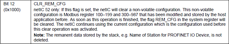
A new flag REM_CFG (bit12) has been spend in the status register to indicate that the netIC has loaded a remanent configuration by the host.
If you want to delete the remanent configuration written by the host you must use the new defined flag CLR_REM_CFG (bit12) in the command regsiter.
Once you have stored the configuration you activate it eather by setting the INIT flag or RESTET the netIC with the Reste FlagTherefore, this function has been deactivated for the netIC 52, at product release.